| |
|
|
| |
|
 |
| |
|
|
 |
| |
|
 |
| |
|
| Background:
|
|
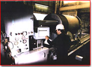
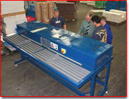
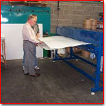
| The wire winding machine shown opposite is
part of a pre-stressed pipe making plant in Toomebridge, N. Ireland.
This machine winds tensioned wire onto concrete pipes (dia. range
400mm ~ 1980mm up to a maximum length of 5m.) |
 |
|
| |
|
|
| |
|
There are three main machinery components in the pipe plant :
- The roller suspension "making-machine" uses rotating moulds
to manufacture the core part of a pipe with a preset internal diameter and
longitudinal pre-stressed bars.
- The wire winding machine applies pre-stessing to a pipe by
wrapping pre-stressed wire around the outside of the core pipe.
- The mortar "coater" machine covers the pipe and
wire with a mortar finish to provide protection.
As part of a full machine design re-appraisal, ITI
compiled a complete set of engineering fabrication drawings for the
framework and operational components of the winder, incorporating many
refinements in comparison with the original design. In particular, the
hydraulically-operated regenerative wire-winding system was assessed with
a view to re-design using modern componentry. As a result of this, the
budget for replacement of the total machine was brought down to the level
originally quoted by contractors for supply of hydraulic machinery components
only.
ITI has since been requested to conduct a similar exercise on a second larger
wire-winder owned and operated by Macrete. As part of that contract, we
would anticipate replacement of an existing mechanical tensioning system
with a hydraulic system as specified for the smaller winder. Electronic
control of a variable displacement hydraulic motor will also improve
considerably the ease of adjustment of the machine for winding core pipes
of varying outside diameters.
|
| |
|
|
| |
|
The Wire Winding Process
|
| |
|
A 6mm high yield steel wire is wrapped several times around a tensioning wheel
which in turn is attached to a high torque hydraulic motor. Oil from the motor
is at the same time driving a second motor which turns the pipe. The rotational
torque of the two motors is then used to generate a tension in the wire as it
winds onto the outside of the rotating pipe. A second wheel moves linearly
along the length of the pipe, thus allowing the tensioned wire to be wrapped
around the pipe at the 'pitch' required. (See thumbnail animation opposite).
|
|
 |
| Thumbnail animation of a wire winding machine |
|
| |
|
Back to top |
|
| |
|
 |
| |
|
Background:
|
| |
|
|
Testing of engines for compliance with growing legislation is an
increasingly important element in any overall internal
combustion engine research and development programme.
Such testing has become more and more sophisticated
through recent years as demands have risen for more precise
and more extensive information on all aspects of engine
behaviour. It
would not now be uncommon, for example, for a test team to
wish to measure and record as many as sixteen simultaneous
signals for temperature, pressure, mass flow rate,
crank-position and
|
|
 |
|
| |
|
force from an engine test-bed – and
this at acquisition rates of several Mega-Hertz and at
levels of accuracy of better than +/-0.5%.
This places very stringent requirements indeed on any
test cell data acquisition system, and especially where
small high-speed high performance engines are concerned. |
| |
|
|
| |
|
The Internal Combustion Engines Research Group (ICERG) of the Mechanical
Engineering Department, Q.U.B. has been involved for many
decades in the testing and development of internal combustion
(IC) engines, and particularly high performance motorcycle
engines. Through
that time, the Group has earned an extremely high worldwide
reputation in this area, having notable success in modelling of
IC engines and catalysts. To capitalise on this proven research
ICERG have teamed up with Optimum Power Technology Inc.
(Pittsburgh, USA) to market a range of powerful software tools,
now used widely by many of the big names in engine and catalyst
development..
|
| |
|
|
| |
|
 |
|
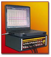
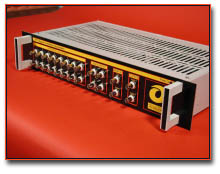
Front view of rack system
|
However, the software developed by ICERG and OPT represents only part of
the solution to the overall problem. They recognised a high
potential demand in the global market for affordable integrated
data acquisition systems.
Furthermore, they recognised that the QUB software could
form one key element in a complete and very flexible commercial
package as good as any presently available throughout the world.
For this reason, over a period of two years or so, ITI
has been leading in the development of Signal Conditioning Units
(SCUs) for a complete engine data acquisition and signal
analysis system package for use potentially in IC engine testing
cells throughout the world. (This work has been greatly assisted
by the winning of Smart grant assistance from Invest NI and DTI.)
|
| |
|
|
The high specification of such electronic
hardware, combined with a low-to-mid target price, puts great
demands on the designers. Through this and other projects, ITI has
developed expertise in many areas of electronic systems design and
product development, and have demonstrated new methods of using
existing technology coupled with new technologies to provide powerful solutions to
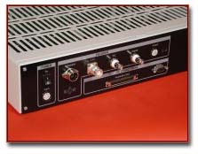
complex problems. The unique system features
include:
|
 |
|
Rear View of rack system
|
|
|
|
|
| |
|
-
Programmable anti-aliasing filters with self-tracking, manual and by-pass
modes;
-
Programmable shaft-encoder
multiplier/interpolator to increase angular resolution to
hundredths of a degree;
-
Simultaneous Sample-and-hold on all analogue
channels;
-
Portable and Rack-mounted system formats;
-
Acquisition of 16 differential analogue
channels at up to 1.25MSPS;
-
Full PC control of system via serial interface
(upgradeable firmware).
|
| |
|
All-in-all the SCU takes advantage of low cost PC
hardware and advanced electronics to produce a unique high-speed
data acquisition system capable of sampling up to 1.25 MHz in
either time-based or angle-based mode. The system provides
automotive engineers with significant savings in both cost and
time over other available systems due to its ease of use and
unique filtering system. Its break-through software controlled
digital filtering system ensures that the correct level of
filtering is applied to prevent aliasing of the incoming signals
regardless of the engine speed. |
| |
|
Back to top |
|
| |
|
 |
| |
|
Background:
|
| |
|
|
Corriboard is a popular rigid plastic material similar in structure
to corrugated cardboard. It is commonly used now to make a very wide
variety of recyclable packaging and storage containers for education and
industries such as automotive, fisheries and food etc..
For many years the client company has produced Corriboard based
products, with the majority of the box shaped products requiring a
seam to be welded shut to form a stable box. |
 |
The technique used for several years was based on spot-welding using
ultrasonics. While this method gave a satisfactory mechanical joint, it did
leave unsightly depressions in the seam where the ultrasonic heads pressed
together. The company was finding that some customers were
hesitant about the products as a result. The technique of using ultrasonic heads was also
inherently
slow and expensive in terms of the capital cost of the welding equipment.
With the assistance of Manufacturing Technology Partnership (MTP), the
company approached ITI to investigate solutions. ITI worked through two
initial stages, the first including provisional research into suitable jointing
techniques and five concept designs, and the second taking one
conceptual design using hot air to a more detailed level. The second stage report also offered an
approximate 'time and materials' budget for the work and a review of the technologies
and hardware options best suited to the selected welding concept.
As a result of the above work, ITI was asked to design, manufacture and
commission a Hot-Air Welding Machine for the client company.
The Concept:
The function of the Hot-Air welding machine is to form a continuous weld in
a two layer overlap of Corriboard plastic. The range of Corriboard gauge is
from about 3mm to 8mm. |
| |
|
|
| |
|
The Welding Process |
| |
|
|
The machine operates on the principle of directing a constant flow of
hot-air between and onto the two plastic surfaces to be welded together.
A suitable shaped nozzle tucks between the overlaped surfaces, directing
the hot air through several pre-heat slots and out the end of the nozzle. The
surface layer of exposed plastic becomes molten, allowing the layers to be
fused together by two stages of pinch rollers which follow the nozzle. |
|
 |
The material is automatically fed past the nozzle thus forming a continuous
joint. When the flat Corriboard box leaves the machine the weld is sufficiently
cool to maintain the joint against abuse.
Read more about the KBC machine at the MTP
website.
|
| |
|
Back to top |
|
| |
|
 |
| |
|
Background:
|
| |
|
|
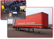
The client was a manufacturer of a wide variety of trailers for the haulage
industry, including trailers which are constructed on what is known as a
‘lightweight’ chassis. From time to time in the past, the company
had
encountered occasions where these 3-axle lightweight trailer chassis
had
developed cracks at particular points in the welded high-tensile chassis
structures. The company therefore decided to instigate a research exercise to
pinpoint the causes of the localised cracks. |
|
 |
|
ITI was approached to assist in the capture of data that could ultimately be supplied
to a Finite Element (FE) model of the chassis to allow fine-tuning of the chassis
design to resolve the material failure problems. To do this ITI had to conceive a means
of instrumenting the trailer sufficiently to capture the pertinent stresses, and a series
of rigorous tests to allow for accurate interpretation of the captured data.
The lightweight trailer was fitted with a total of 20 No. strain gauges, 2 No. air
suspension pressure transducers, 1 No. wheel speed pickup, and 2 No.
inclinometers, all
placed to maximise the useful data obtained. The signals were captured on a notebook
computer during the tests and post processed.
A series of tests was also devised and carried out on the trailer to obtain data suitable for
calibration of the various sensors and to verify any assumptions made.
Three ‘Road Runs’ provided for extensive sets of dynamic test data. The runs
included a ‘chicane’ test, roundabout manoeuvre, rough and smooth road
tests, and tight turns, amongst others. The data obtained from the static tests provided
the basis for correct interpretation of the data observed during the dynamic tests.
An immense amount of valuable information was obtained from the above work, much
of which could be applied to improve the chassis design with or without the use of FE
modelling.
The graph shown below is a short extract from the second Road Run (dynamic testing),
showing the measured stresses in the top & bottom leaf-spring strain gauge sets
both nearside and offside. Numbered points are highlighted where particular road
features correlate with data. The bottom trace on the graph
indicates the trailer speed
(km/hr).
- Feature 1
- Tight left turn at 10 km/h and stationary for 22 seconds
- Feature 2
- Tight right turn at 5 km/h
- Feature 3
- Tight right turn at 18 km/h
- Feature 4
- Tight left turn at 20 km/h
- Feature 5
- Tight left turn at 15 km/h
|
| |
|
Back to top |
|
| |
|
Copyright © Innovation Technologies (Ireland) Ltd 2001-2004 |